Configuring Cisco Secure PIX Firewall 6.x and Cisco VPN Client 3.5 for Windows
with Microsoft Windows 2000 IAS RADIUS Authentication (working addon...)
- Second:
I have extended the configuration with a DMZ-interface since you normally
would have such an interface for your servers (web, mail etc.).
- Third:
Some of the information in the document is wrong: Correct the following:
In the PIX Firewall Configuration section correct the following:
wrong:
| PIX Firewall |
access-list 101 permit ip 10.1.1.0 255.255.255.0 10.1.2.0 255.255.255.0
nat (inside) 0 access-list 101
|
A complete configuration for a 3-interface setup would be:
| PIX Firewall |
      pixfirewall(config)# write terminal
Building configuration...
: Saved
:
PIX Version 6.1(1)
nameif ethernet0 outside security0
nameif ethernet1 inside security100
nameif ethernet2 dmz security90
enable password YouReallyWish encrypted
passwd YouWish encrypted
hostname pixfirewall
domain-name mycompanydomain.dk
fixup protocol ftp 21
fixup protocol http 80
fixup protocol h323 1720
fixup protocol rsh 514
fixup protocol rtsp 554
fixup protocol smtp 25
fixup protocol sqlnet 1521
fixup protocol sip 5060
fixup protocol skinny 2000
names
name 14.36.100.30 mywebserver
name 14.36.100.31 mymailserver
access-list acl_out permit icmp any any
access-list acl_out permit tcp any host mywebserver eq www
access-list acl_out permit tcp any host mymailserver eq smtp
access-list acl_out permit tcp any host mymailserver eq pop3
access-list acl_dmz permit icmp any any
access-list acl_dmz ip any any
!--- Access-list to avoid Network Address Translation (NAT)
!--- on the IPSec packets to host on inside-interface.
access-list acl_nonat2inside permit ip 172.18.124.0 255.255.255.0 10.1.2.0 255.255.255.0
!--- Access-list to avoid Network Address Translation (NAT)
!--- on the IPSec packets to host on dmz-interface.
access-list acl_nonat2dmz permit ip 192.168.1.0 255.255.255.0 10.1.2.0 255.255.255.0
!--- Access-list to use split-tunneling (NAT).
access-list acl_vpnclient_split permit ip 172.18.124.0 255.255.255.0 10.1.2.0 255.255.255.0
access-list acl_vpnclient_split permit ip 192.168.1.0 255.255.255.0 10.1.2.0 255.255.255.0
!--- Access-list for access rights for the VPN Client.
access-list acl_vpnclient permit 10.1.2.0 255.255.255.0 172.18.124.0 255.255.255.0
access-list acl_vpnclient permit 10.1.2.0 255.255.255.0 192.168.1.0 255.255.255.0
pager lines 24
logging on
logging timestamp
logging buffered informational
!--- Remember NOT to set interfaces to autosense.
interface ethernet0 100full
interface ethernet1 100full
interface ethernet2 100full
mtu outside 1500
mtu inside 1500
mtu dmz 1500
ip address outside 14.36.100.1 255.255.0.0
ip address inside 172.18.124.1 255.255.255.0
ip address dmz 192.168.1.1 255.255.255.0
!--- Some extra instrusion detection taken from a
!--- book from Cisco.
ip audit name idsattack attack action alarm drop reset
ip audit name idsinfo info action alarm
ip audit interface outside idsinfo
ip audit interface outside idsattack
ip audit info action alarm
ip audit attack action alarm
ip local pool ippool 10.1.2.1-10.1.2.254
pdm history enable
arp timeout 14400
global (outside) 1 14.36.100.51
global (dmz) 1 192.168.1.253
nat (inside) 0 access-list acl_nonat2inside
nat (inside) 1 172.18.124.0 255.255.255.0 0 0
nat (dmz) 0 access-list acl_nonat2dmz
nat (dmz) 1 0.0.0.0 0.0.0.0 0 0
static (dmz,outside) 14.36.100.0 192.168.1.0 netmask 255.255.255.0 0 0
static (inside,dmz) 172.18.124.0 172.18.124.0 netmask 255.255.255.0 0 0
access-group acl_out in interface outside
access-group acl_dmz in interface dmz
route outside 0.0.0.0 0.0.0.0 14.36.1.1 1
timeout xlate 3:00:00
timeout conn 1:00:00 half-closed 0:10:00 udp 0:02:00
   rpc 0:10:00 h323 0:05:00 sip 0:30:00 sip_media 0:02:00
timeout uauth 0:05:00 absolute
aaa-server TACACS+ protocol tacacs+
AAA-server RADIUS protocol radius
!--- Defining the AAA server as a RADIUS server and identifying
!--- the IP address.
AAA-server partnerauth protocol radius
AAA-server partnerauth (inside) host 172.18.124.196 cisco123
   timeout 5
no snmp-server location
no snmp-server contact
no snmp-server community public
no snmp-server enable traps
floodguard enable
sysopt connection permit-ipsec
no sysopt route dnat
crypto ipsec transform-set transsetdyn esp-3des esp-md5-hmac
crypto dynamic-map dynmap 10 set transform-set transsetdyn
crypto map vpnmap 10 ipsec-isakmp dynamic dynmap
!--- Enables the PIX to launch the Xauth application on the VPN
!--- Client.
crypto map vpnmap client configuration address initiate
crypto map vpnmap client authentication partnerauth
crypto map vpnmap interface outside
isakmp enable outside
isakmp identity address
isakmp policy 10 authentication pre-share
isakmp policy 10 encryption 3des
isakmp policy 10 hash md5
isakmp policy 10 group 2
isakmp policy 10 lifetime 86400
vpngroup vpn3000 address-pool ippool
vpngroup vpn3000 dns-server 10.1.1.2
vpngroup vpn3000 wins-server 10.1.1.2
vpngroup vpn3000 default-domain mycompanydomain.dk
vpngroup vpn3000 split-tunnel acl_vpnclient_split
vpngroup vpn3000 idle-time 1800
vpngroup vpn3000 password ********
telnet timeout 5
ssh timeout 5
terminal width 80
Cryptochecksum:3f9e31533911b8a6bb5c0f06900c2dbc
: end
[OK]
pixfirewall(config)#
|
Configuring Cisco VPN Client 3.5 for Windows
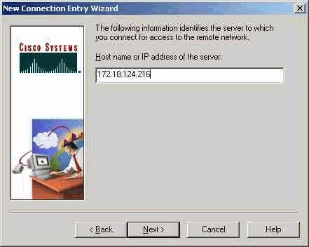
- Launch the VPN Client and click New to create a new connection.
- In the Connection Entry box, assign a name to your entry.
- Enter the IP address of the public interface of the PIX.
- Under Group Access Information, enter the group Name and the group
Password.
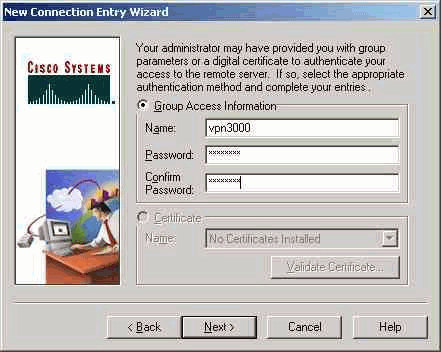
- Click Finish to save the profile in the registry.
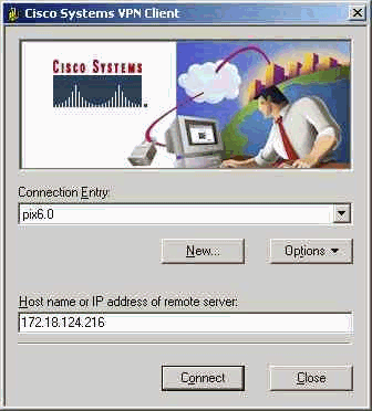
- Click Connect to connect to the PIX.
Configuring the Microsoft Windows 2000 Server with IAS
This is a very basic setup to use a Windows 2000 IAS server for RADIUS authentication
of VPN users. If you require a more complex design, please contact Microsoft
for assistance.
Note: These steps assume that IAS has already been installed on the
local machine. If not, please add this through Control Panel > Add/Remove
Programs.
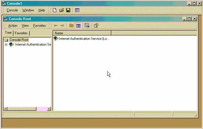
- Launch the Microsoft Management Console by going to Start
> Run and typing "mmc" and then clicking OK.
- To add the IAS service to this console, go to Console > Add
Remove Snap-In...(Ctrl+M).
- Click Add. This will launch a new window with all of the available
standalone snap-ins. Click on Internet Authentication Service (IAS)
and click Add.
- Make sure Local Computer is selected and click Finish. Then
click Close.
- Notice that Internet Authentication Service is now added. Click OK
to see that it has been added to the Console Root.
- Expand the Internet Authentication Service and right-click on Clients.
Click New Client and input a name. The choice of name really does not
matter; it will be what you see in this view. Make sure to select RADIUS
and click Next.
- Fill in the Client Address with the PIX interface address that the
IAS server is connected to. Make sure to select RADIUS Standard and
add the shared secret to match the command you entered on the PIX:
AAA-server partnerauth (inside) host 172.18.124.196 cisco123 timeout
        5
Note: cisco123 is the shared secret in this case.
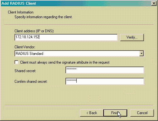
- Click Finish to return you to the Console Root.
- Next, you need to modify the users to allow connection. Go to Console
> Add/Remove Snap-in. Click Add and then select the Local
Users and Groups snap-in. Click Add. Make sure to select Local
Computer and click Finish. Click OK.
- Expand Local User and Groups and click the Users folder in
the left pane. In the right pane, double-click the user you want to allow
access.
- Click the Dial-in tab and select Allow Access under Remote
Access Permission (Dial-in or VPN).
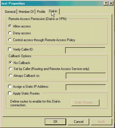
- Click Apply and OK to complete the action. You can close the
Console Management screen and save the session, if desired.
- The users that you modified should now be able to access the PIX with the
VPN Client 3.5. Please keep in mind that the IAS server only authenticates
the user information. The PIX still does the group authentication.
- Now, in Local User and Groups and click the Groups folder in
the left pane. Create a new group and give it the Group name: Access for VPN.
Add all the users that you have allowed Remote Access Permission and
click Create and Close.
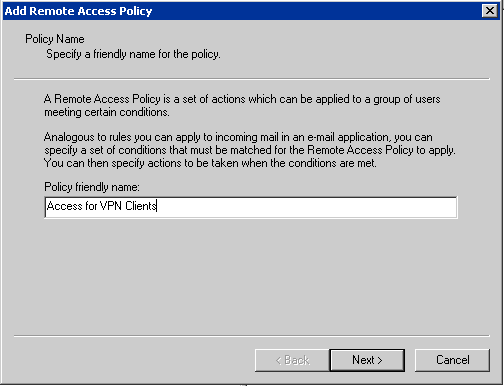
- Go back to your Internet Authentication Service management interface and
click on Remote Access Policies. Right-click and choose New Remote Access
Policy. Give the policy the name Access for VPN Clients and click Next.
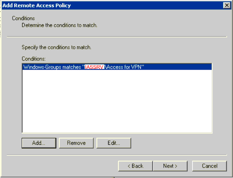
- In the conditions windows click Add and choose Windows-Group and click
Add. In the Groups window click Add and choose the Access for VPN-group
you have just created and click Add OK and OK.
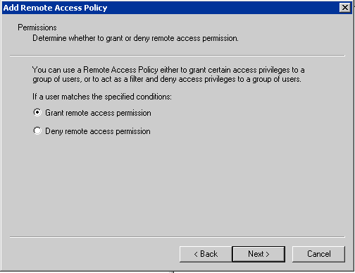
- Click Next and select Grant remote access permission and click Next.
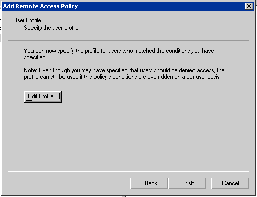
- Click on Edit profile.
- Go to the Authentication tab. Under
Authentication Methods, make sure only Unencrypted Authentication
(PAP, SPAP) is checked.
Note: The VPN Client can only use this method for authentication.
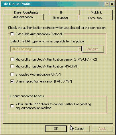
- Click Apply
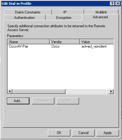
- Click on the Advanced tab. Under Parameters - remove ALL entries.
Click Add and select Cisco-AV-Pair from the list and click Add.
In the Multivalued Attribute Information window click Add and type
acl=acl_vpnclient as the Attribute value. Click OK and OK
and Close and Apply and OK and Finish to close the
Remote Access Policy wizard.
- You done!
Troubleshooting: If the user authentication fails try to add the domain in front of the user name ie. MYDOM\myusername
in stead of just myusername. This can be the case if the IAS server is on another domain than the user account or if
the IAS server is a member of a domain and you are using a local user from the IAS server.
If you have any questions or comment, please email me at ciscosupport@saltbaek.dk.
God luck!
Some contents are Copyright © 2002 Cisco Systems,
Inc. The rest: Bjarne Saltbaek, Kraks Forlag AS.